
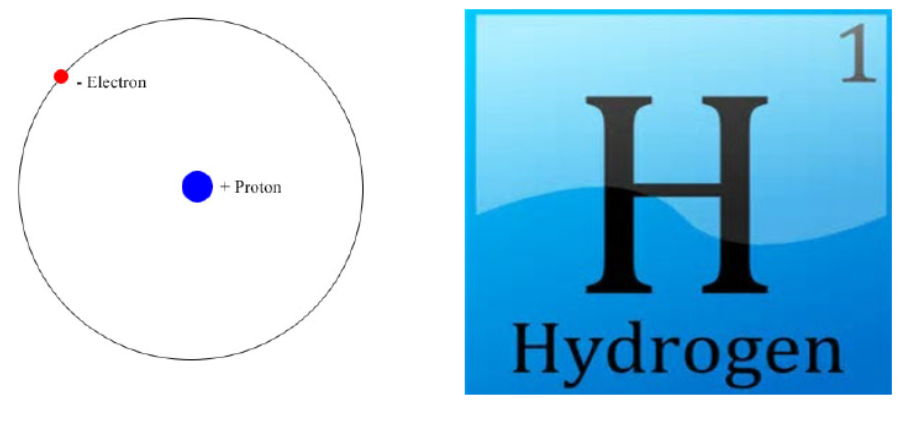
Hydrogen is the lightest element in the periodic system. It has only one proton and one electron. The hydrogen molecule connects two hydrogen atoms. See Figure below.
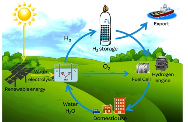
In the reaction with oxygen to water, the chemical energy is released. The other way around, by electrolysis, using energy you can split water in hydrogen and oxygen

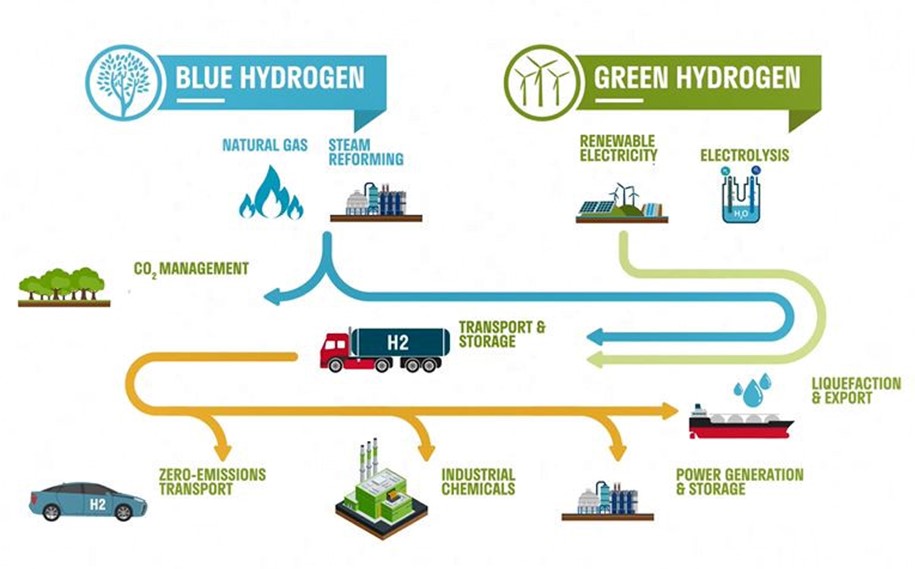
For the transition to the green hydrogen economy, blue hydrogen is an option where not enough green hydrogen is available. See Figure below.
Figure above shows the green hydrogen cycle which only uses green energy and emits no CO2. This should be our green future of hydrogen. However most of the hydrogen produced now uses natural gas and thus emits CO2. Blue hydrogen is the third option in which the CO2 is captured and stored underground.
Once produced, hydrogen can be stored and transported more or less similar to other gasses and as a gas can be burned for high temperature industry processes and can be converted to electrical power in for example mobility applications.
As more and cheaper hydrogen will come available it becomes a very good alternative for battery electric vehicles. What the future will bring is a result of a complex process where both technologies are challenging each other. It is crucial for every application to choose the best solution. Here hydrogen is favorable in case large power is needed for a long time. For example in relative long distance road transport.
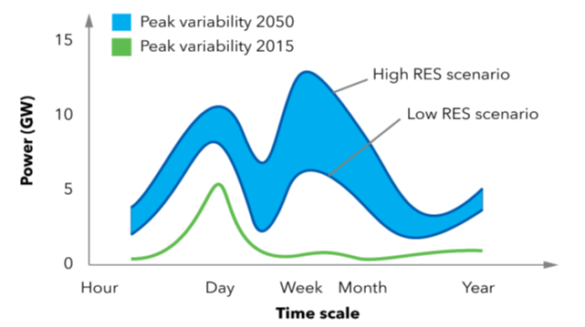
Figure above shows that, while increasing the share of renewable energy, also the variations in production will become larger and over a longer time scale. This means that large buffers for also a longer time scale are needed to balance the production and use of green energy.
fig 4.5
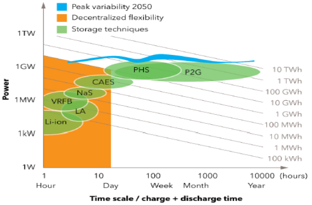
Possibilities for buffering are shown in Figure 4.5. On search for a buffer that can store very much energy for a long time and can also supply high power Power 2 Gas (P2G) is the most promising solutions. And the gas here is hydrogen.
As hydrogen will become more available the price will go down which will makes in more competitive with the other energy carriers like fossil fuels and batteries.
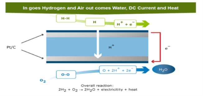
For mobility applications fuel cell technology is used to convert the chemical energy to electrical power and heat. Also internal combustion engines have been developed with hydrogen as fuel and are still and again in development. For now this reader will focus on the main stream fuel cell technology using Proton Exchange Membrane Fuel Cells (PEMFC). Figure above shows the chemical process again. For one cell with typical voltage of 0,6 V.
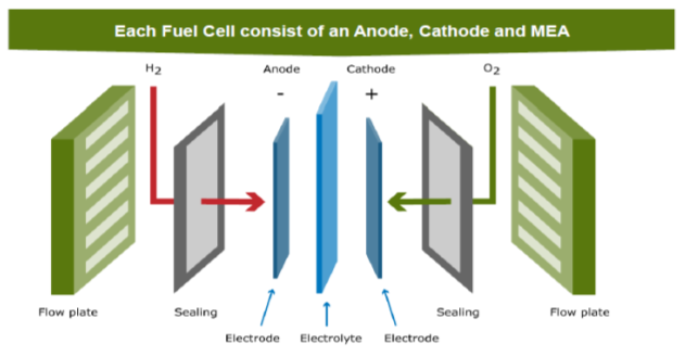
The components of the cell are shown In Figure 4.7 : the electrolyte (or polymer membrane) separates Anode and Cathode. Using the flow plates hydrogen flows to the Anode and oxygen flows to the cathode.
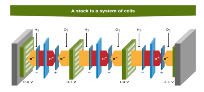
To increase the voltage level we put the cells in serie: this is the stack (see Figure 4.8). More details will follow later on the FCCP fuel cell.
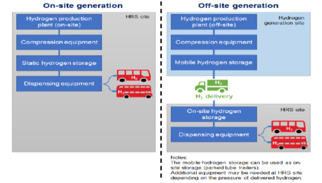
Hydrogen filling stations can replace fossil fuels filling stations. The advantage is that filling a car takes then approximately the same time as we are used to now. Hydrogen can be transported using a tube trailer or be made on-site using green energy. See Figure above. In case a natural gas infrastructure is available this could also be used for distributing the hydrogen to the filling stations.

Following the road map for hydrogen in mobility applications, presented in Figure 4.10, it is clear that in all fields the vehicles have been introduced already. In the ambitious scenario the deployment will in most applications in the near future! Or is already there here in the North Netherlands where hydrogen busses are widely used already!
Safety (Figure below) is important using hydrogen like it is for each energy carrier.
You cannot see or smell hydrogen… and hydrogen is highly flammable, very explosive and easy to ignite. Safety awareness and action is therefore very important. Doing so hydrogen can be used in a safe way.

Restricted area (FCCP project members; For the links: please login on the FCCP teams site)
The theoretical base consists of:
- K00: Introduction to hydrogen technology: link
- K01: Fuel cell systems: link
- K02: Fuel cell supply: link
- K03: application in mobility: link
- K04: safety hydrogen and workshop design: link
- K05: high voltage safety , not applicable
- K06: Fuel Cell vehicles>> Integrated in K03
- K07: Workshop design>> Integrated in K04
- V01: Safety procedures>> Integrated in K04
